Nowadays, structure analysis and design are performed by using software. In the software, we analyze and design the structure as a frame instead of a separate structural element (i.e. slab, beam, and column), and, get the most accurate result in the minimum time. However, to interpret the design result, a designer must have a complete know-how of the design of each element (i.e. slabs, beam, column, and foundation) separately.
In the previous articles, I covered the basis of the design of slab and footing. In this article, I am discussing the basis of the design of the beam (i.e. flexural element). Hope it will be helpful for beginners.
The structure design of the reinforced Concrete beam is discussed below:
Minimum Depth of the Beam
First, determine the minimum depth of the beam as per the minimum depth specified in the ACI code (Refer to Table 1):
| Support condition | Minimum Depth |
| Simply supported | L/16 |
| For one end continuous | L/18.5 |
| For two-end continuous | L/21 |
| Cantilever | L/8 |
Applied Loads on the Beam
Dead Loads
- Self-weight of beam
- Self-weight of beam in KN/m = unit wt of concrete × width of the beam × height of the beam.
- Slab dead load
- Slab dead load (i.e. self wt of slab, finishes, etc.) is transferred as a dead load on the beam
If slab is one way;

Slab dead loads transferred on Longer beams in KN/m = Slab dead load (KN/m2) * Lx / 2
Slab dead loads transferred on shorter beams in KN/m= 0
If slab is two way;
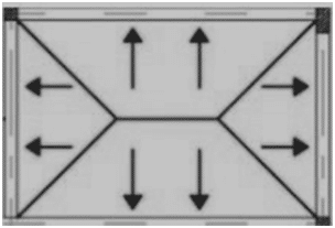
Maximum Slab dead loads transferred on Longer beams in KN/m = Slab dead load (KN/m2)*Lx/6 *((3-(Lx/Ly)^2)
Maximum Slab dead loads transferred on Shorter beams in KN/m = Slab dead load (KN/m2) * Lx / 3
Here;
Ly is the longer dimension of slab
Lx is the shorter dimension of slab
Note: you can use the calculator available at this link”https://knowledgesharingplatform.com/load-distribution-from-slab-to-beam/”
- Wall load.
Wall weight in KN/m = unit wt of material × thickness of wall × height of wall
For wall load calculation, you can use the calculator available at “https://knowledgesharingplatform.com/calculate-wall-weight-in-kn-m-kg-m-lb-ft/”
Live Load
Slab live load transferred on longer beams and shorter beams will be calculated as explained under the heading “slab dead load”.
Lateral Loads and Moments
Lateral load and moments due to lateral force are applied on a beam due to frame action, these loads and moments are generated due to the following:
- seismic
- Wind
- Equipment or piping loads
Note: calculation of these lateral forces and moments will be covered in a separate blog
Miscellaneous Others Load (if applicable)
Following others, load (concentrated or uniformly) will be calculated and applied on a beam (if applicable) according to their nature (dead or live ):
- OHWT weight
- Any equipment weight
- Cantilever slab reaction
- Pipe and cable support
- Platform load
Ultimate Loads on the Beam
Calculate ultimate loads (Wu) for the ultimate load combination specified by ACI 318M or any other applicable codes & standards.
Ultimate Forces and Moments
- Maximum Shear (at a distance d from the face of Support)
- Maximum negative moment (Hogging)
- Maximum positive moment (Sagging)
- Points of contra flexure(i.e. required for reinforcement curtailment)
- Draw critical sections, for reinforcement optimization (For example, this 4m long beam has 3 critical sections due to a change in the value of both support moments)

However, you can also cover this design in two sections, by providing the same reinforcement at both ends.
Check Beam section is Singly Reinforced or Doubly Reinforced
- Pickup the highest value of ultimate moment Mumax either bottom (+ve) moment or top(-ve) moment
- Calculate Rumax
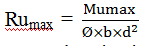
Here; = strength reduction factor taken as 0.9 for flexure
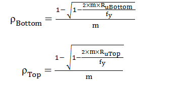
- Calculate ρ

- Calculate ρb

- Calculate ρmax = 0.634ρb for fy=416Mpa
- If ρ < ρmax OK, the section will be designed as singly reinforced and there is no requirement for compression reinforcement.
- If ρ > ρmax, change the cross-section of the beam, especially increase the depth of the beam(if possible), so, that ρ < ρmax and the beam can be designed as singly reinforced, otherwise, design the beam as doubly reinforced (i.e. section having compression reinforcement). The design of a doubly Reinforced beam will be covered in the upcoming blog; whereas, it is not a cost-effective method.
Design of Singly Reinforced Section
Flexure Design
- Calculate Ru for negative (-ve) moments and positive (+ve) moments of each critical section

Here; = strength reduction factor taken as 0.9 for flexure
- Calculate ρrequired for both the top and bottom of each section using the below formula
- Calculate ρmin of each section using below mentioned formula:

ρmin2 = 1.33ρrequired (i.e. ρBottom or ρTop)
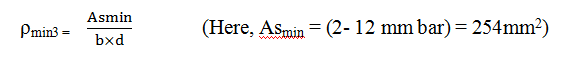
ρmin= Maximum of (minimum(ρmin1,ρmin2),ρmin3 )
- Check ρBottom or ρTop of each section > ρmin, otherwise, take ρBottom & ρTop= ρ
- Calculate the area of steel at bottom = max (ρBottom, ρmin)×b×d
- Calculate the area of steel at the top = ρmin×b×d
- Calculate extra steel at top support = (ρTop – ρmin ) × b ×d
you can also use the calculator for reinforcement calculation, which is available on this link “https://knowledgesharingplatform.com/flexural-reinforcement-calculator-as-per-code-aci-318m/”
Shear Design
- Pick up maximum ultimate shear Vu from the beam analysis result
- Calculate ØVc =

- Calculate ØVc/ 2
- If Vu < ØVc / 2, there is no need to provide shear reinforcement.
- If ØVc / 2 < Vu < ØVc , means Vs = 0 only minimum shear reinforcement is required, Shear reinforcement spacing is calculated from the below formula ;

Smax=maximum ( d/2, 600 mm)
Sprovided = minimum (S1, Smax)
Here;
Avmin = 2× (Area of 10-mm bar)
Smin =Spacing between the stirrups in mm.
d= effective depth of the beam
fc and fy are in Mpa
- If Vu > ØVc, then Shear reinforcement is required. However, first check ;

, otherwise, increase the cross-section of the beam.
- Calculate the shear to be carried by shear reinforcement (Vs) from the below formula:

- Calculate spacing between the stirrups using Vs

- Calculate spacing using Avmin.

- Check if

then Smax= maximum ( d/2, 600 mm),otherwise, Smax=maximum ( d/4, 300 mm)
- Sprovided = minimum (Srequired,S1, Smax)
Note:
- All design formulas are in metric system and based on ACI 318 M code
- Doubly Reinforced design is not discuss in this blog.
- Torsion is not considered on the beam
Leave a Reply