An individual footing that transfers loads from a single column/pedestal to the soil is known as “Isolated Footing”. Isolated Footing may be rectangular, square, or circular.
Following are the steps involved in the design of “Isolated Footing”:
Calculation of Applied Loads
Calculate Loads acting on the footing. Which can be;
- Vertical loads
- Horizontal loads
- Direct Moments
- Moments due to Lateral loads
- Moments due to eccentricity
Determination of Footing Area
Determine the area of footing by taking trial values of Length, width, and thickness of footing and calculate maximum and minimum base pressure.
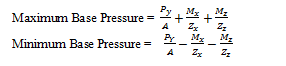
Here ;
“P” is the vertical load
“A” is the trial area of the footing
“Mx” and “Mz” are the algebraic sum of all moments in the considered direction Direct moment (if any)+Moment due to horizontal loads (if any)+Moments due to eccentricity of vertical loads(if any)
“X “and “Z” are the Horizontal axis and “Y” is the vertical axis.
Note:
- Here All loads are in service state
- Choose the size on which the maximum base pressure is less than and nearest to the “Allowable soil bearing capacity”.
- In normal practice, minimum base pressure shall be kept ≥ 0 to avoid top reinforcement in the isolated foundation.
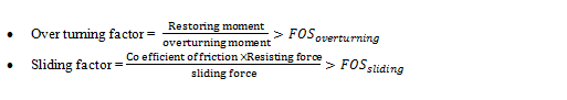
Sliding and Overturning Check
Check footing stability against sliding and over-turning in both axes.
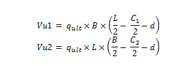
Here;
“d” is the effective depth of the footing
L and B are the footing dimension
C1 and C2 are the column dimensions
3- Check Vu1 < ØVc1 and Vu2 < ØVc2 otherwise increase the thickness of footing (i.e. Normal practice), otherwise provide shear reinforcement.
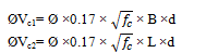
Here;
fc is the cylindrical compressive strength of concrete in Mpa
Two way Shear Check
1-Check the provided footing thickness in two-way shear.
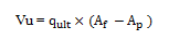
- Determine punching area (Ap)
- Calculate punching shear Vu
3. Calculate ØVc
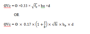
Here;
bo is the Punching Parameter
4- Check Vu > ØVc, otherwise increase footing thickness
Check the Development Length of Column Reinforcement
Check the provided footing thickness as per the minimum requirement of the development length of column reinforcement.
Reinforcement Calculation
1-Calculate the ultimate moment in both directions, from below mentioned formula
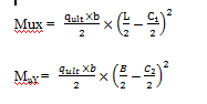
Here ;
b is the unit strip of 1m = 1000 mm
2- Calculate Ru (in Mpa) for maximum moments.(MuX OR MuY )

3-Calculate steel ratio (ρ)
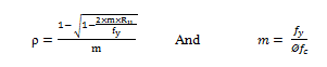
Here;
fy is the yield strength of reinforced steel
4- Calculate Area of steel (in mm2/m)
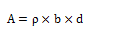
5- Calculate minimum area (in mm2/m) of steel.
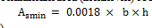
(For fy ≥ 420Mpa otherwise, factor 0.018 will be changed)
6- Compare As with Asmin and select the greater values. If Asmin governs then no need to do the calculation for another direction and provide minimum in both directions, but As govern then repeats the calculation for another direction.
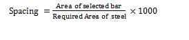
7- Select suitable diameter of the bar and calculate the spacing of bars (in mm)
Note:
- Design formulas are as per ACI Concrete code
- All formulas are given in the Metric system
- The factor of safety and strength reduction factor value will be taken as per the latest edition of ACI code