A cantilevered beam is a type of beam that is fixed at one end and free at the other. It is commonly used in structures like balconies, bridges, and overhanging roofs. When loads are applied to this beam—like point loads or a uniformly distributed load (UDL)—they cause internal forces in the beam. These internal forces can be understood using shear force and bending moment diagrams for a cantilevered beam.
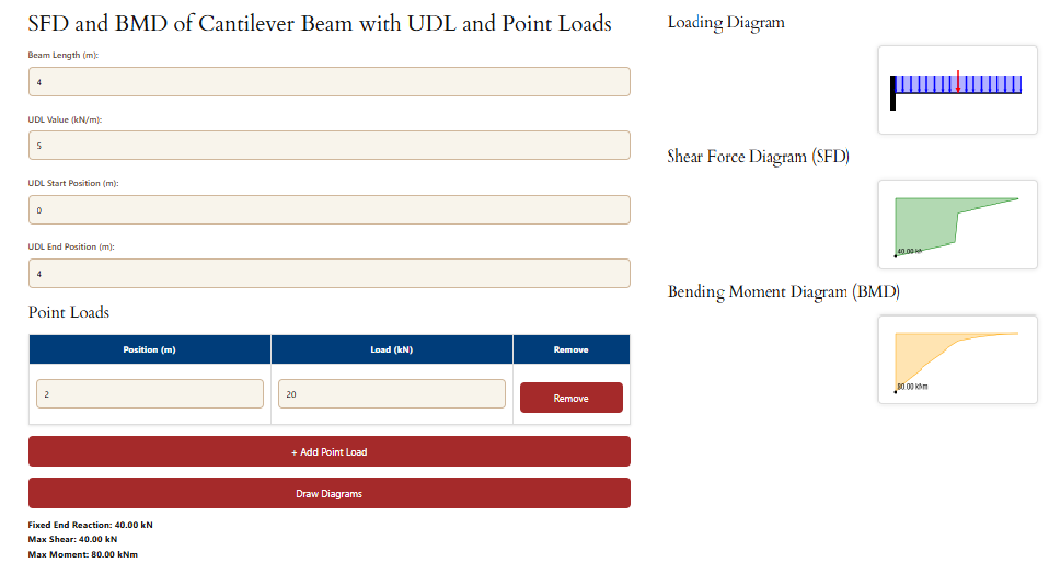
This tool helps you create these diagrams easily. You can change the beam length, add point loads at different locations, and apply a UDL over any section of the beam. Once you input the values, it will draw three diagrams: the loading diagram, the shear force diagram (SFD), and the bending moment diagram (BMD).
The shear force diagram shows how the vertical force changes along the beam. The bending moment diagram shows how the bending effect changes along the beam. These diagrams help engineers understand where the beam experiences the most stress so they can design it safely.
By adjusting the loads, you can instantly see how the shear force and bending moment change. This makes it a powerful visual tool for learning and design.

Understanding these diagrams is key to building strong and safe structures. With this tool, you get quick feedback and a clear picture of what’s happening inside the beam.
SFD and BMD of Cantilever Beam with UDL and Point Loads
Point Loads
| Position (m) | Load (kN) | Remove |
|---|
Loading Diagram
Shear Force Diagram (SFD)
Bending Moment Diagram (BMD)
Related Posts
If you found this post on shear force and bending moment diagrams helpful, be sure to explore our other analyses covering different beam types and loading scenarios:
- https://knowledgesharingplatform.com/shear-force-and-bending-moment-diagrams-for-simply-supported-beam-with-vdl/
- https://knowledgesharingplatform.com/shear-force-and-bending-moment-diagrams-for-cantilever-beam-with-vdl/
- https://knowledgesharingplatform.com/shear-force-and-bending-moment-diagrams-of-simply-supported-beam-having-udl-point-load/
These resources will help you better understand the behavior of beams under various loads and supports.

Leave a Reply